
ISAFE Methodology : Generalized Components
|
A highly structured conceptual framework (theory of multifactor flight domains) used to formalize the problem of flight safety research into complex situations. |
|
|
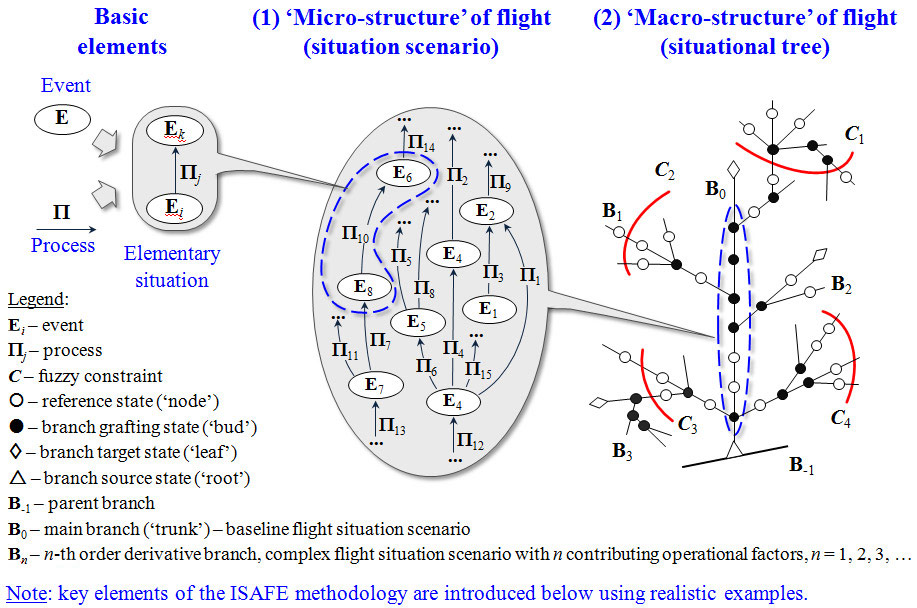
A two-level knowledge model of flight, which includes:
|
|
|
A flight scenario scripting language in the form of events and processes used to quickly formalize the content and logic of any multifactor situation for simulation. |
|
|
High-precision mathematical equations and computational algorithms of the system dynamics model, which describe:
|
|
|
An interrelated set of unified data structures designed to accommodate input (‘parametric definition’), interim and output data flows of the system model. |
|
|
Algorithms for automatic ‘mining’ of safety knowledge from virtual ‘flights’. |
|
|
A design-of-experiments technique is used to plan autonomous fast-time simulation experiments on a PC, ‘plant’ and control the growth of a situational tree. |
|
|
A family of color-coded knowledge maps designed to ‘granulate’ and represent high-level (‘bird’s eye view’) knowledge on the safety of a complex operational domain. |
|
|
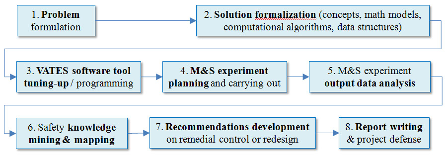
An integrated, standardized process of MS& based flight safety research: |
The Purpose
The purpose of the ISAFE methodology is to formalize a M&S and AI based approach to proactive accident risk analysis and prevention – during aircraft lifecycle, from design to operation:
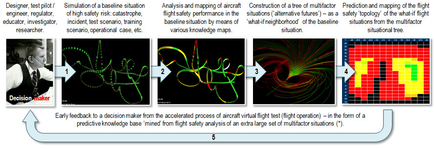
In this approach, the ‘pilot/ automaton – aircraft – operating environment’ system dynamics model is employed as a ‘generator’ of missing statistics on flight accidents/ incidents in multifactor or unknown situations.
The model is implemented as a ‘single-platform’ software solution – VATES technology.
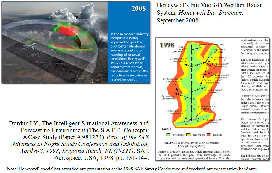
ISAFE Methodology Concept Origination and Similar Concept
Onboard Implementation: Chronology
Two-Level Knowledge Model of a Multifactor Flight Domain
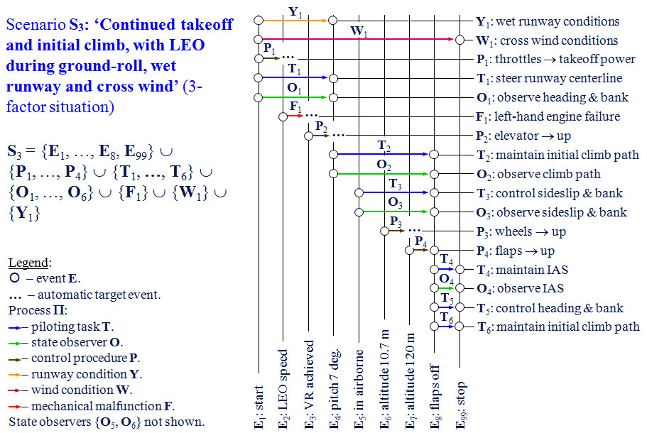
Flight Situation Scripting Language – Discrete-Continuous Formalism : Definition of Key Concepts
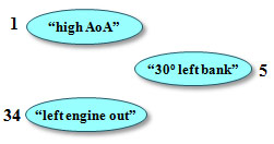
Flight event (E)The flight event is a special state of the system which is important to the pilot/designer in terms of flight control ‘switching’ logic and stands for a substantial change in the flight situation. Examples: – “left engine out”
|
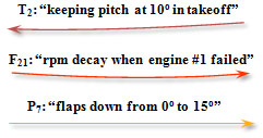
Flight process (П)The flight process is a time-history of one or several flight parameters which characterize a continuous aspect of the ‘pilot (automaton) – aircraft – operating environment’ system behavior (dynamics, control, weather, etc.). Examples: – “steer runway’s centerline”
|
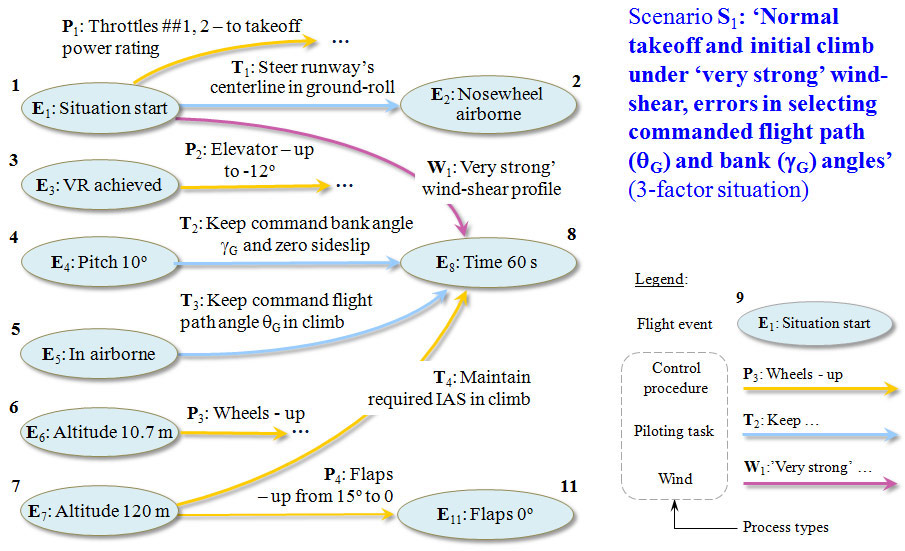
Flight scenario (S)The flight situation scenario is a concise plan of a flight situation. It specifies the content and the logic of flight in this situation. A flight scenario is depicted as a directed graph or a matrix. Examples: – “normal takeoff”
|
| NB: Flight situations of any complexity for any aircraft and any phase of flight can be described using events and processes (since 1977). | ||
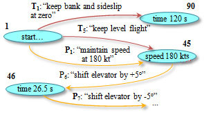
Graphic Representation of Complex Flight Situation Scenario –Directed Graph Format
Graphic Representation of Complex Flight Situation Scenario –Matrix Format
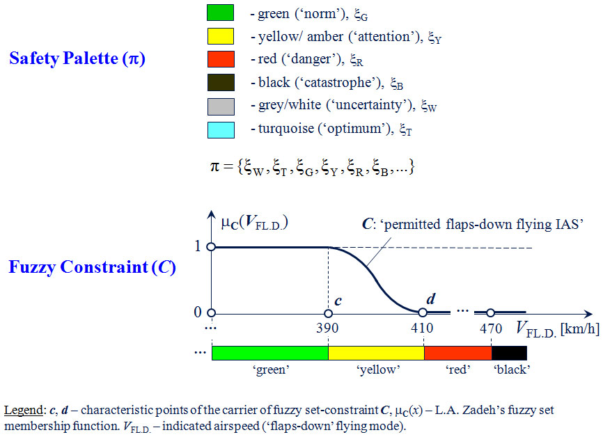
Safety Palette. Fuzzy Constraint
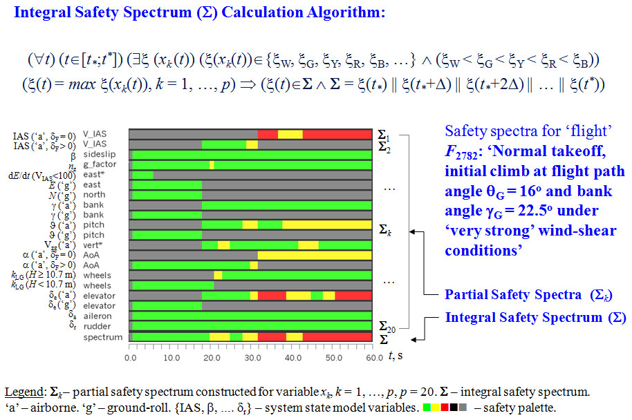
Partial Safety Spectra. Integral Safety Spectrum
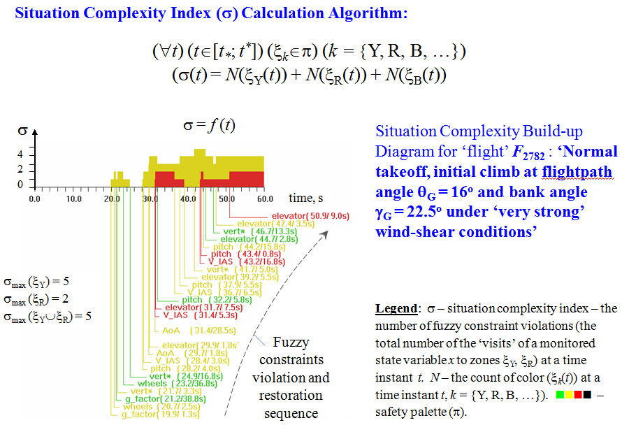
Situation Complexity Build-up Diagram
Design Field of Multifactor Operational Hypotheses
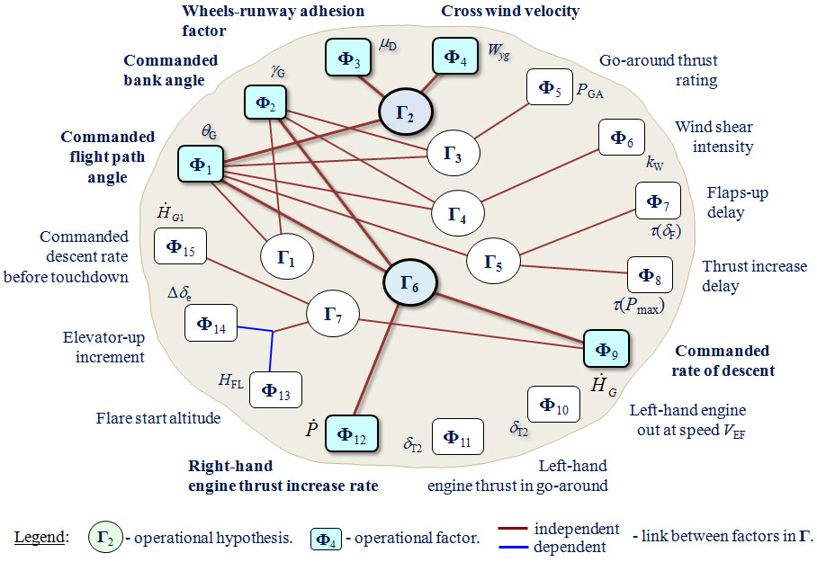
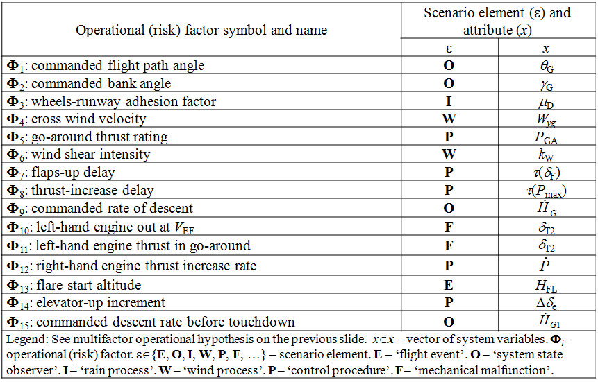
Operational (Risk) Factors for Testing
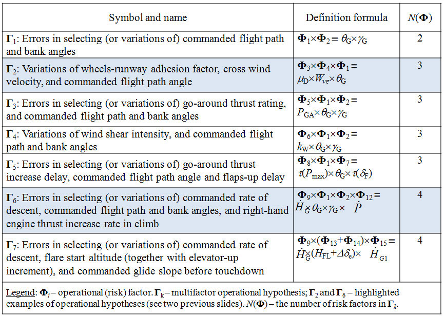
Multifactor Operational Hypotheses
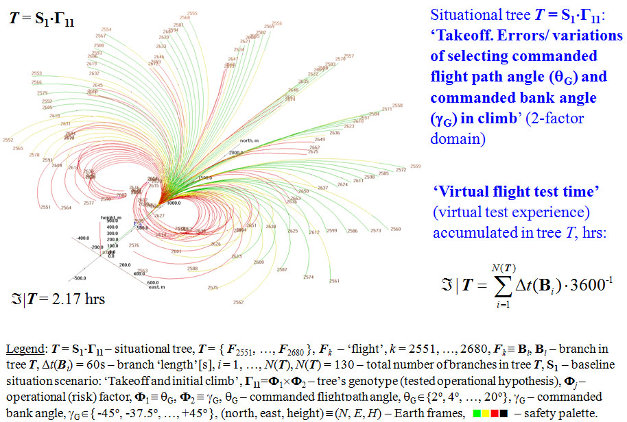
Situational Tree of Flight. Virtual Flight Test Time
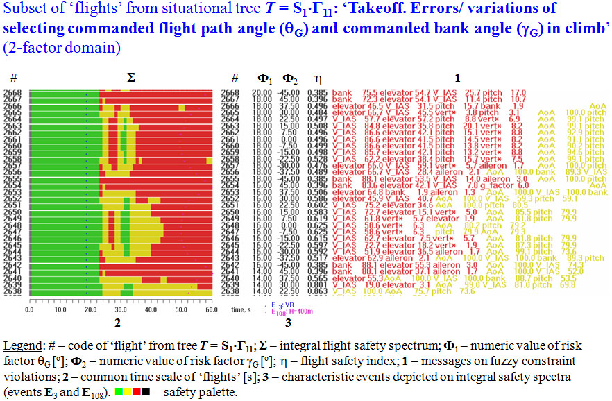
Integral Safety Spectra. Examined Operational (Risk) Factors.
Flight Safety Indices. Fuzzy Constraints Violation Statistics
Flight Situation Safety Classification Categories
|
Color |
Code |
Name |
Definition |
|
Green |
I |
Safe |
The system state resides mainly inside the ‘green’ zone. As a maximum, the system state may stay, for a short period of time, in close proximity to the operational constraints, i.e. inside the ‘yellow’ zone, but must leave it by the end of the situation. |
|
Salad |
II-A |
Conditionally Safe – a |
As a maximum, the system state may stay temporarily, or for a medium period of time, in close proximity to the operational constraints, i.e. inside the ‘yellow’ zone. |
|
Yellow |
II-B |
Conditionally Safe – b |
As a maximum, the system state may stay for a long period of time in close proximity to the operational constraints, i.e. inside the ‘yellow’ zone. |
|
Orange |
III |
Potentially Unsafe |
As a maximum, the system state may violate operational constraints, i.e. enter the ‘red’ zone, for a short or between short and medium period of time, but must leave it by the end of the situation. |
|
Red |
IV |
Dangerous (Prohibited) |
As a maximum, the system state may stay beyond the operational constraints, i.e. inside the ‘red’ zone, for a medium or long period of time or till the end of the situation. |
|
Black |
V |
Catastrophic (‘Chain Reaction’) |
There is at least one (i.e. for a very short time) occurrence of the violation of any operational constraint on the ‘black’ level. |
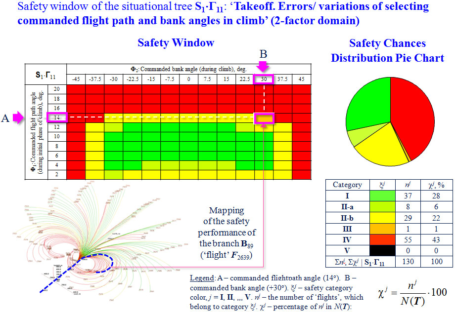
Safety Window. Safety Chances Distribution Pie Chart
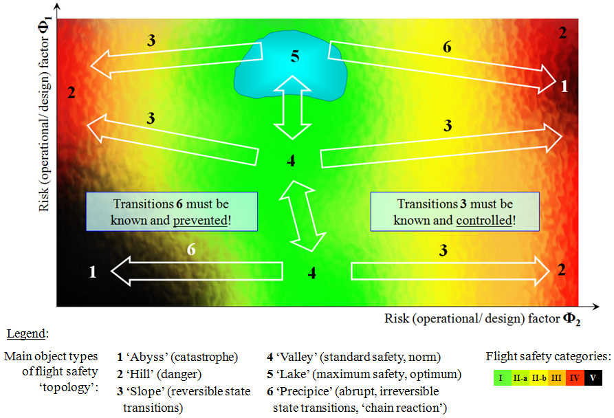
Flight Safety ‘Topology’
| << Previous page | Next page >> |